

Rhapsody is my idea of a modular amateur radio transceiver. Imagine a combination of modern SDR architecture with the expandability of a personal computer and the construction style of old HF radios. The project will consist of a motherboard with slots for modules. The minimum for a functional device will be a Zero-IF board and a DSP board. Further modules can add band-pass filters, intermediate frequency, upconverters for higher bands, and downconverters. Since the project will be open source, you or other members of the community can create custom modules or replace the old ones with new versions without changing the whole transceiver. Don't expect the cheapest solution; multiple PCBs will certainly add to the cost of the whole device, but the flexibility and upgradability might be worth it. What is more, such an approach is friendly for experimenters and the environment.
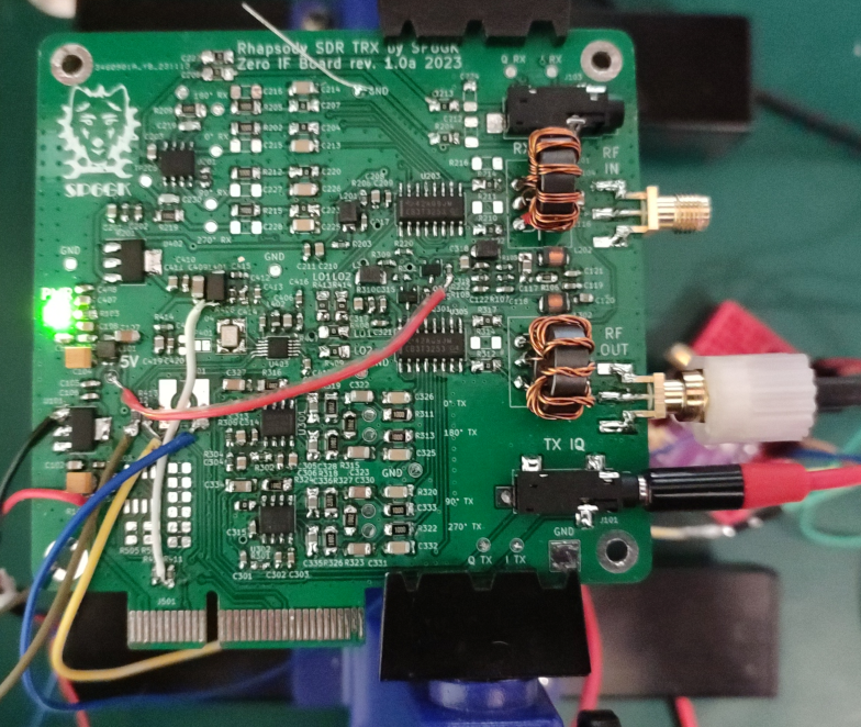
So far, I have created and tested the prototype of the Zero-IF board and obtained good results. I have successfully demodulated and modulated the SSB signal across the whole HF spectrum using Zero-IF board and STM32F407 microcontroller with a 24-bit ADC and DAC. This board uses a Tayloe mixer in both receive and transmit configurations. In receive mode, the input is a 50 Ohm terminated RF port that can be hooked up to an antenna or other RF frontend stage (or IF output), and the output signal is a 3.5mm jack with I and Q signals. The I and Q signals represent the IQ modulation that is fed to the ADC. Then, the microcontroller processes the IQ according to the phasing method so that LSB or USB audio is extracted and then passed to DAC. The reverse of the process is implemented for the transmitter chain.
Below, I present some results of opposite sideband suppression that you can expect from this board and DSP setup alone with nothing else. I am now working on designing the DSP board and the motherboard to ease the development since handling separate ADC/DAC, MCU, and Zero-IF board on the bench is quite problematic.
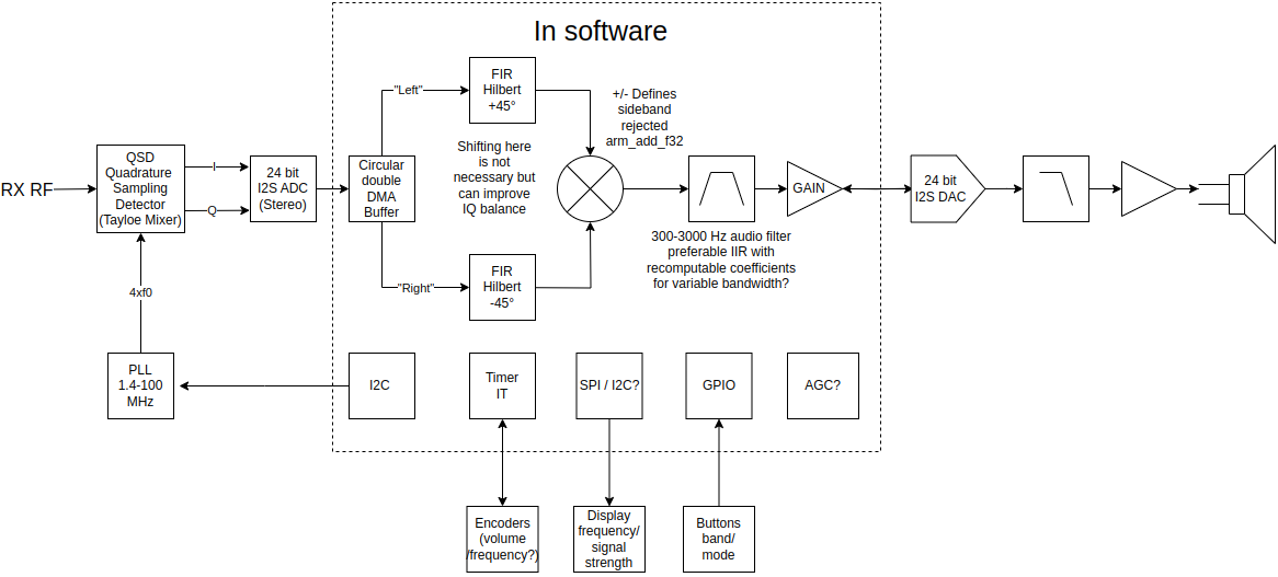
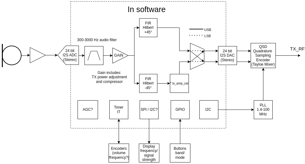
Figures above present the general block diagram of the transmit and receive path. Because bulk od the signal processing is realized in digital domain it is easy to redirect the path and to perform different algorithms on the data. Current version utilizes CMSIS-DSP library on STM32F407 microcontroller. The data from ADC and to DAC is transfered over I2S interface. I am considering switching to Raspberry PI and using FFT and IFFT instead of the FIR/IIR filter to create a selectrive SSB audio filter.
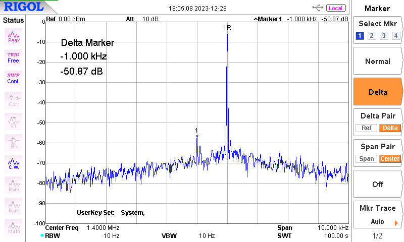
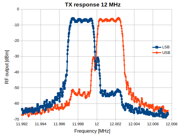
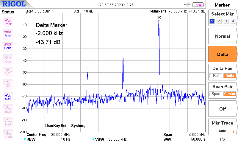
Ideally the I and Q signals would have identical amplitudes and exact 90 degree phase difference. In reality because of components imperfections some IQ balance is always present, this limits the carrier and opposite sideband suppression. First I have measured the transmitter using the spectrum analyzer with VFO set to different frequencies.
At work I had the opportunity to perform some measurements of the receive path. At this
stage I have also added DSP code for demodulation of AM and FM. SINAD was measured using Rohde Schwarz CMS 57 radio test set which was also used as one of the signal generators. The second generator was the Siglent SSG 3021X. No distinction here is made between CW and SSB since the demodulator uses the same algorithm, the only difference in the final product would be the more narrow band pass filter in case of CW.
Measurement methodology and acceptance limits will be based on ETSI EN 300 676 which is an European standard for aviation VHF radio communication equipment using amplitude modulation. This is quite a high bar to meet but it ensures high quality of professional equipment that has to work in harsh conditions including congested spectrum with high dynamic range of neighboring signals which is common both in amateur radio and in aviation.
Sensitivity was tested by directly providing either a CW (in case of SSB) or modulated signal to the input port of the zero IF board. In the microcontroller the RX_Vol variable was set to 128. Signal level from the RF generator was adjusted until 12 dB SINAD was measured by the radio tester. An additional experiment was conducted in which RX_vol was set to 1000, in the case of SSB, sensitivity has increased by 3 dB. This is most likely not worth this gain because such a wide span of AGC might be difficult to control reliably.
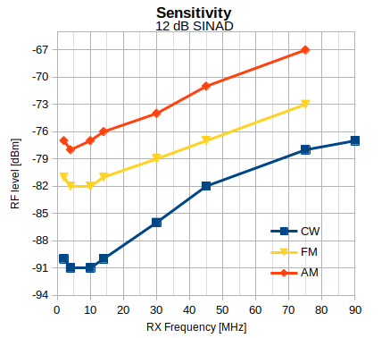
In the plot of sensitivity it can be noticed that the best results were achieved between 4 and 14 MHz. This coincides with the bandwidth of the input transformer (see page 31 of presentation attached below).
achieved gain is nothing special, some changes to the resistor network in Tayloe mixer could be made in order to increase the gain. However, in this project the goal is to add an analog front end with LNA and stepped attenuators so that AGC will maintain proper RF input level to the zero IF board.
ETSI EN 300 676 specifies that sensitivity shall not exceed -101 dBm, as it is receiver requires an additional LNA to achieve sensitivity better than -101 dBm.
Desensitization is a phenomenon where a receiver is deafened in the presence of a strong neighbouring signal. In this test two generators were coupled using a combiner. Then the first generator was tuned to a receiver frequency and the RF level was set so that receiver produced 12 dB of SINAD. Then the second generator was switched on and tuned to another frequency, its RF level was increased until the SINAD of received audio had diminished to 6 dB. Difference between generator's levels was noted as desensitization.
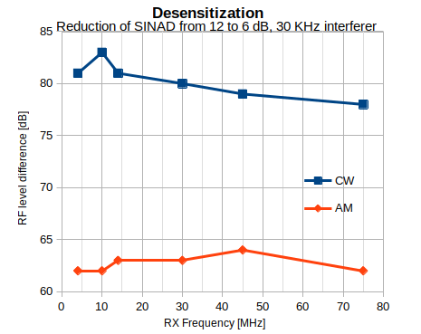
At 1 MHz offset interfering signal had to be at least 91 dB higher to desensitize the receiver. Measurement was also repeated at 4 and 30 MHz but for each data set the difference was not higher than 2 dB so the desensitization is not heavily dependent on the frequency of operation. What is more interesting is that in the case of AM the desensitization is much worse. This might be partially due to the fact that in the DSP, the filtering is wider so overall rejection of signals at 30 KHz might not be that good.
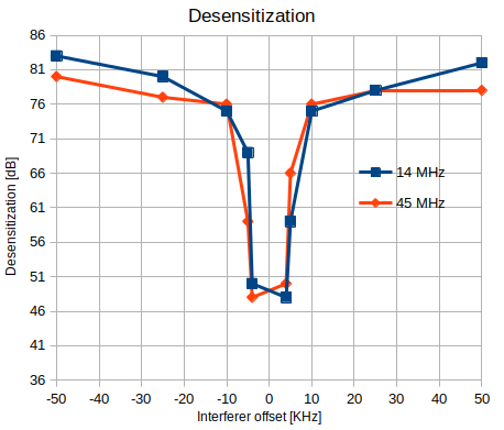
Given the fact that the zero IF board features no input attenuators and no band pass filtering (other than inherent preselection given by the Tayloe mixer) these results are quite good for a direct conversion receiver. One has to however keep in mind that in case of amateur radio usage, the presence of strong commercial stations can still decrease performance, addition of input band pass filters for dedicated amateur radio bands is highly recommended if layout is not a limitation.
ETSI EN 300 676 requires at least 70 dB of desensitization blocking at the offset of +/-1 MHz, performed here measurements provide additional data points that show that the zero IF board can meet this requirement even at 10 KHz offset in CW mode, result is not that good at AM where the receiver fails by about 6 dB. This is still a very good result for such a simple front end.
In this measurement the linearity of the receiver is evaluated by generating two interfering signals. One signal is a constant carrier at the offset of F from the nominal frequency while the second signal is placed at an offset of 2F from the nominal frequency. Nonlinearities in the receiver's signal path will result in mixing leading to production of IMD3 products that will be present at the nominal frequency of the receiver. This spurious signal will be then received as a normal signal would ever be, despite not originating from the "ether". In case of AM the second interferer is also modulated, so that modulation is mirrored to the wanted frequency. Both interfering signals are increased in level until a SINAD of 12 dB is achieved, this level is then compared to sensitivity of the receiver at the nominal frequency. Intermodulation rejection ratio is the difference between sensitivity for 12 dB SINAD and final setting of RF level where the IMD3 is able to produce the same 12 dB SINAD.
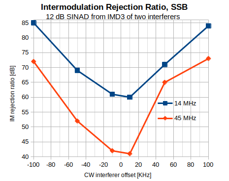
It can be noticed that intermodulation rejection is better at 14 MHz when compared to 45 MHz. This might be related to saturation of ferrite material in the transformer (which is nonlinear and might behave differently at higher frequencies) or this might be the effect of multiplexer used in the Tayloe mixer. SSB offers better performance here by about 6 dB which is not unusual. The amount of frequency components is lower in case of these two CW signals and bandwidth is narrower.
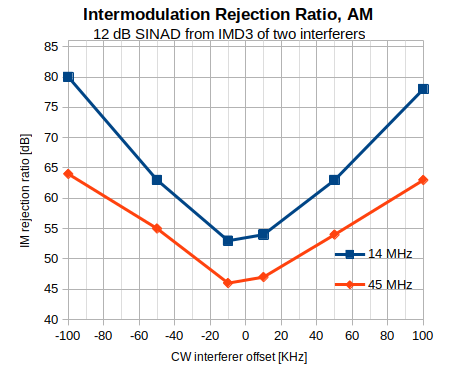
ETSI EN 300 676 requires at least 70 dB of IM rejection at the interferer offset of 100 KHz. SSB passes the ETSI requirements with 2 dB margin at 45 MHz (which is not much when we include manufacturing tolerances) and with 15 dB at 14 MHz which is plenty. For amplitude modulation the receiver passes ETSI limit with 10 dB margin when nominal signal is at 14 MHz but fails by about 5 dB when frequency is increased to 45 MHz.
Cross modulation rejection describes resilience of the AM receiver to presence of strong neighbouring AM signals. Nonlinearities of the receiver will degrade quality of received AM signal when other modulated signal is present in the spectrum. In this measurement the wanted signal level was adjusted to obtain 30 dB SINAD, then the interfering signal was set to another frequency and its level was increased until SINAD of wanted signal had dropped to 20 dB. Difference between generators levels was noted as cross modulation rejection ratio.
At 14 MHz the wanted signal with 1 KHz modulation was set to -45 dBm where 30 dB of audio SINAD was measured. Then at 1 MHz offset the unwanted signal with 400 Hz modulation was increased to 13 dBm where SINAD at the nominal frequency has decreased to 20 dB. This means that the cross modulation rejection ratio is 58 dB (Note: ETSI actually defines difference from maximum sensitivity (ie. 12 dB SINAD)). This measurement was repeated for interferer offset at -1 MHz where cross modulation rejection ratio was measured as 64 dB. There is some asymmetry here but it is not that significant. It is also worth noting the limitations of the measurement setup. Since generators were coupled with 3 dB coupler and 6 dB attenuators at each generator's output the isolation is not perfect and some IMD can occur in the output of the combined signal.
The same measurement was repeated at 45 MHz where for both -1 and +1 MHz 42 dB of cross modulation rejection ratio was measured.
| Center Frequency | Interferer | Cross Modulation Rejection [dB] |
|---|---|---|
| 14 MHz | -1 MHz | 58 |
| +1 MHz | 64 | |
| 45 MHz | -1 MHz | 42 |
| +1 MHz | 42 |
In these measurements interfering signal is adjusted in level until SINAD of wanted signal drops from 12 dB to 6 dB. 25 KHz and 8.33 KHz channel spacings were measured.
| Nominal Frequency | Interferer Spacing | ACR [dB] |
|---|---|---|
| 14 MHz | 8.33 kHz | 49 |
| 25 kHz | 58 | |
| 45 MHz | 8.33 kHz | 40 |
| 25 kHz | 50 |
A little overlooked parameter of every receiver is the conducted spurious emissions. This measurement observes spectrum at the antenna of the receiver. The goal is to determine whether the receiver actually emits RF that might be picked up by other systems. Naturally some emissions are to be expected, in heterodyne receivers we might observe LO and its harmonics at the antenna. If you have more than one receiver on site it can become problematic since you might pick up signals transmitted by other receivers. Such spurious emissions can also reveal the position of the receiver on the battlefield, or.. be used by the government to detect your telescreen TV (allegedly).
Below screenshots show spectrum measured at the antenna as the receiver was tuned to 10 MHz (narrow on the left, wide in the center) and at 30 MHz (on the right).
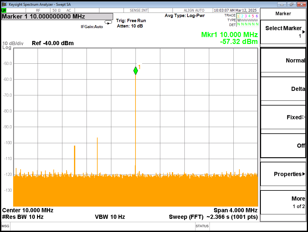
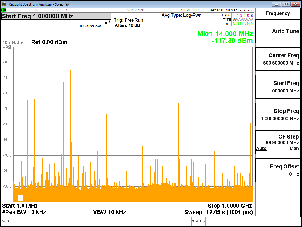
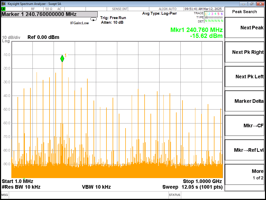
It becomes apparent that the Zero-IF board, if used as a direct conversion receiver alone, presents horrendous spurious emissions at the antenna port. What is worse, because of the switching frequencies of the multiplexer in Tayloe mixer a significant spur is always present at the received frequency. When set to 10 MHz the 10 MHz spur is at -57 dBm. This is not something that front end filtering can eliminate. The only solution is to use an isolation amplifier. I would recommend using an amplifier (perhaps cascode?) that has at least 30 dB of isolation. What is more, the wider span shows that high level spurs are visible well up to 1 GHz. This can be limited by the band pass filters.
Simple dynamic range measurement was performed at 45 MHz. The goal was to determine at which point the receiver starts to compress the audio output. In AM mode, the rx volume was set in SW to 100 (this is a float variable), 12 dB SINAD was achieved at -70 dBm, then level was increased as rx volume variable was decreased (this is manual audio gain control). Volume was adjusted in a way to achieve 68 mV RMS observed at the -70 dBm level. Finally it was observed that the compression starts around -23 dBm. Therefore maximal input level to Tayloe mixer in this configuration should be kept below -23 dBm in order to avoid audio distortion. It might be rare to encounter such a strong signal at your antenna in a countryside base station, however if you operate the transmitter on the other band in close proximity to the receive antenna the isolation can be very small (ex. car installation or contest station) leading to presence of such signals. Therefore, additional front end should include variable or switched in attenuator to protect the zero IF board.
Tayloe mixer offers good performance especially in terms of sideband rejection eliminating the need for a crystal band pass filter that is typically found in the filter method of SSB generation and reception. That being said, special caution has to be put while assembling the board. Low tolerance and high quality RC components should be used to avoid IQ imbalance (see presentation below).
The presented zero IF board offers great flexibility in reception and transmission modes since generation of proper IQ is handled in software. It is also the software that determines the bandwidth of the receiver. Speaking of bandwidth, in comparison to a classical high speed ADC or aliasing receiver, one of the Tayloe's mixer inherent advantages is its tracking preselector. This means that zero IF board has some built in band pass filter like characteristics, this is thanks to the n-path architecture of the mixer which works similarly to switched capacitor filter.
While the board offers good performance when compared to its footprint, price and flexibility there is a lot of area for improvement by addition of analog front end. This is where the mixed architecture of Rhapsody can really shine. Since many measurements proven to give better results at lower frequencies (especially sideband rejection, ACR, IM rejection) it makes sense to convert the RF signal to IF between 4 to 10 MHz and then process it with Tayloe mixer. We loose the tuning flexibility of Tayloe mixer fixing it at one frequency but we can improve parameters like ACR, desensitization and intermodulation rejection by using off the shelve crystal filter for a common frequency. These filter does not need to be sharp enough to improve sideband rejection, just enough to get rid of close in band signals. What is more, adding analog front end with stepped attenuator will improve dynamic range allowing for limiting of RF level before conversion, this is important in amateur radio since signal strength can vary by tens of dB, something that is difficult to handle without very high resolution ADC. Finally, addition of LNA and some isolation amplifier would not only improve sensitivity but also limit spurious emission. In summary, at frequencies below 14 MHz the presented board offers very good desensitization and intermodulation figures. ACR, dynamic range and cross modulation rejection could however use some help from external signal processing.
Tip: you can press down arrow in the upper right corner of the embedded documment in order to download it.

sp6gk 'at' protonmail.com
Here is demonstration of a restored radio from 1938.