

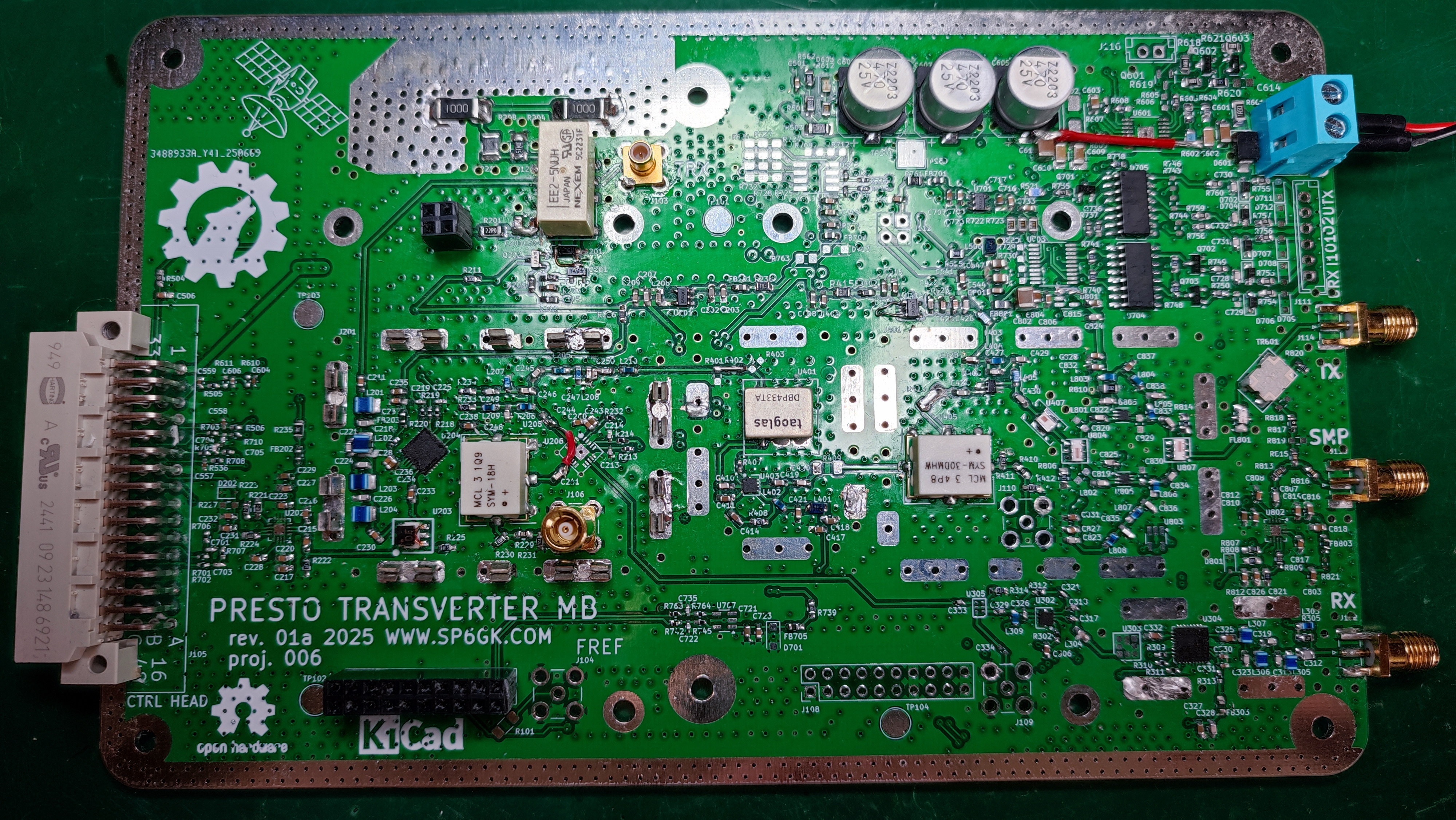
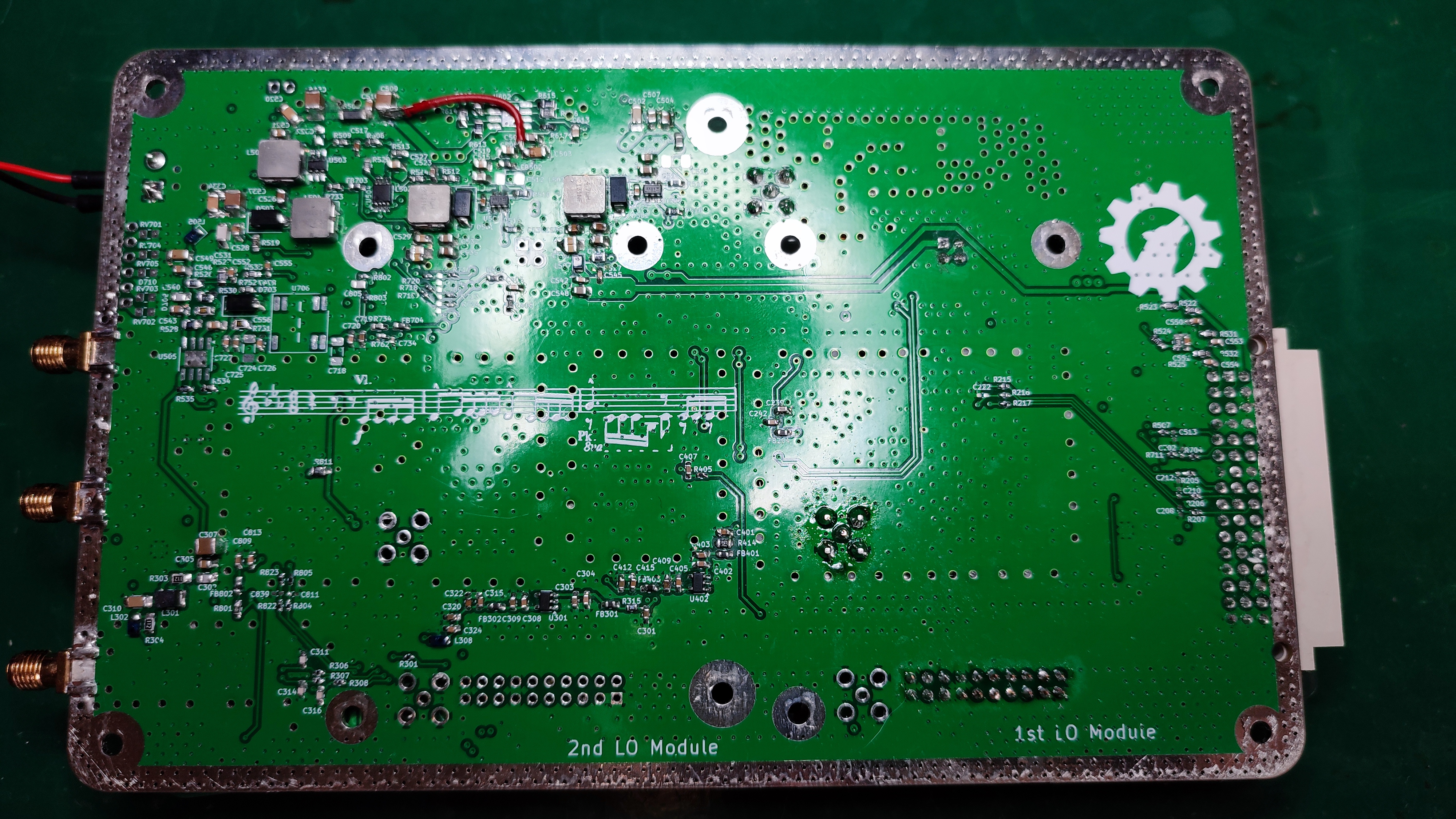
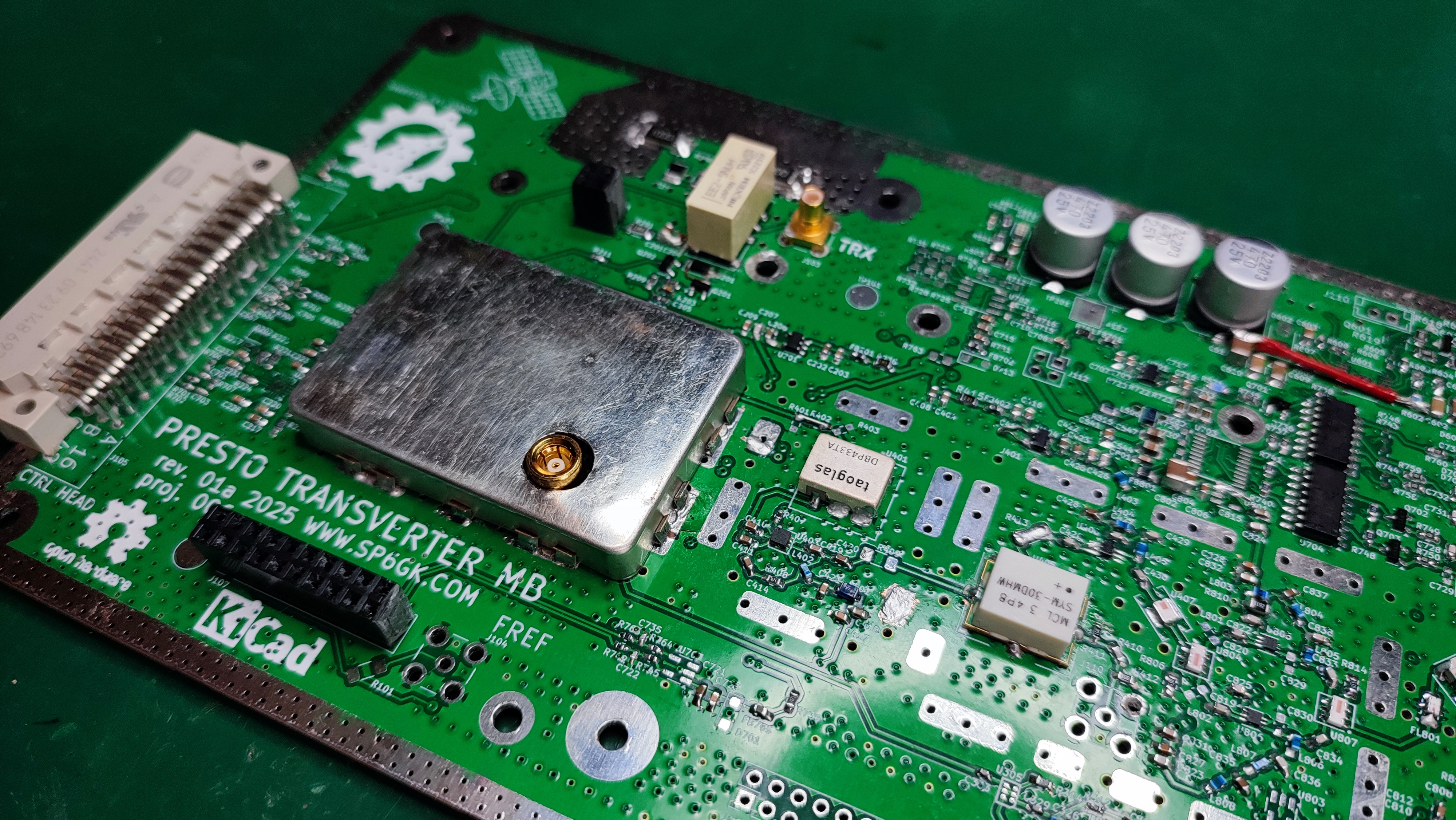
Presto is a transverter that allows you to use a standard 10 m capable transceiver to communicate via the QO-100 satellite. It provides an S-band uplink (2.4 GHz), while the downlink can be received directly on your HF radio, since Presto also processes the signal from the Ku-band LNB.
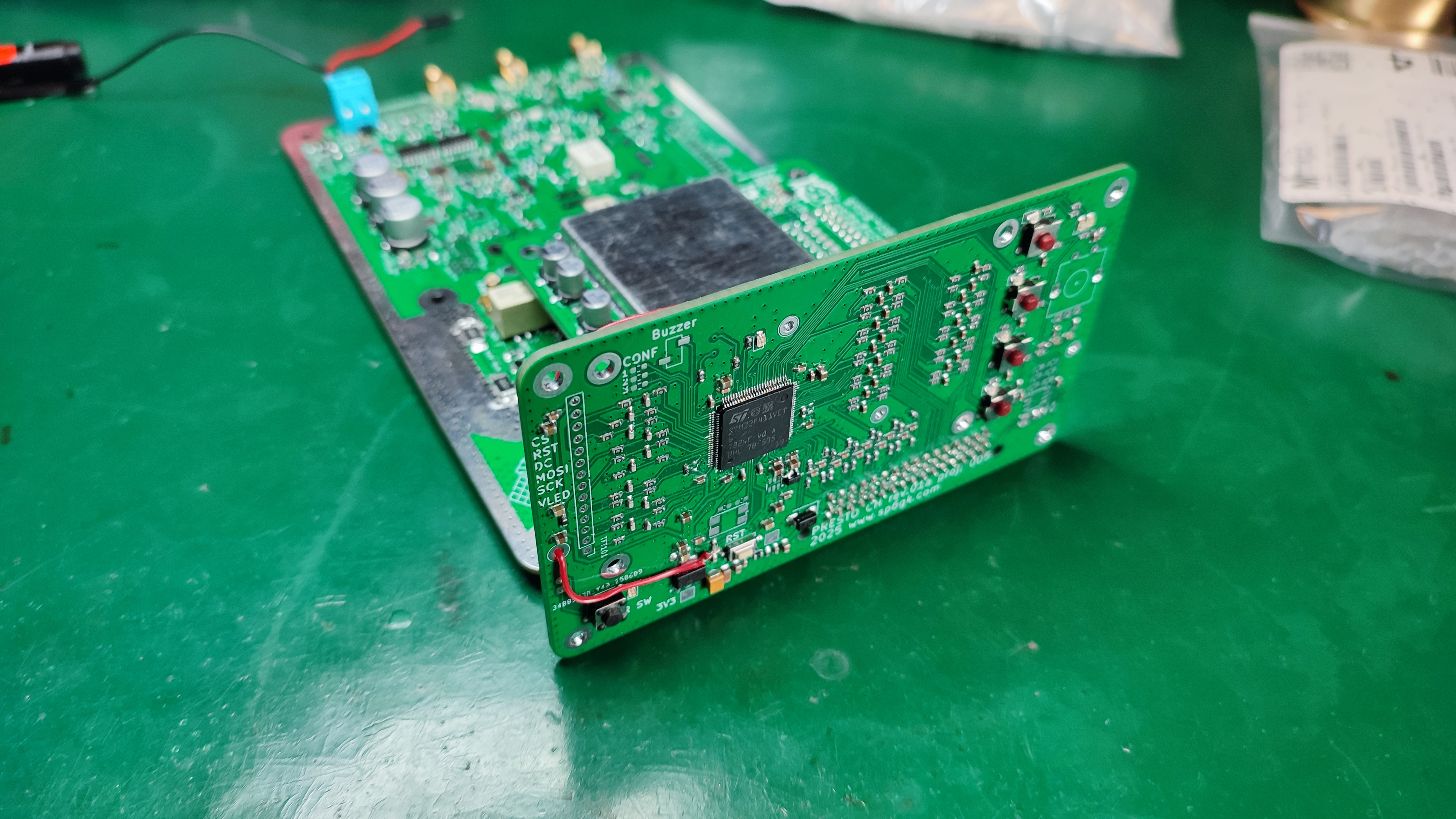
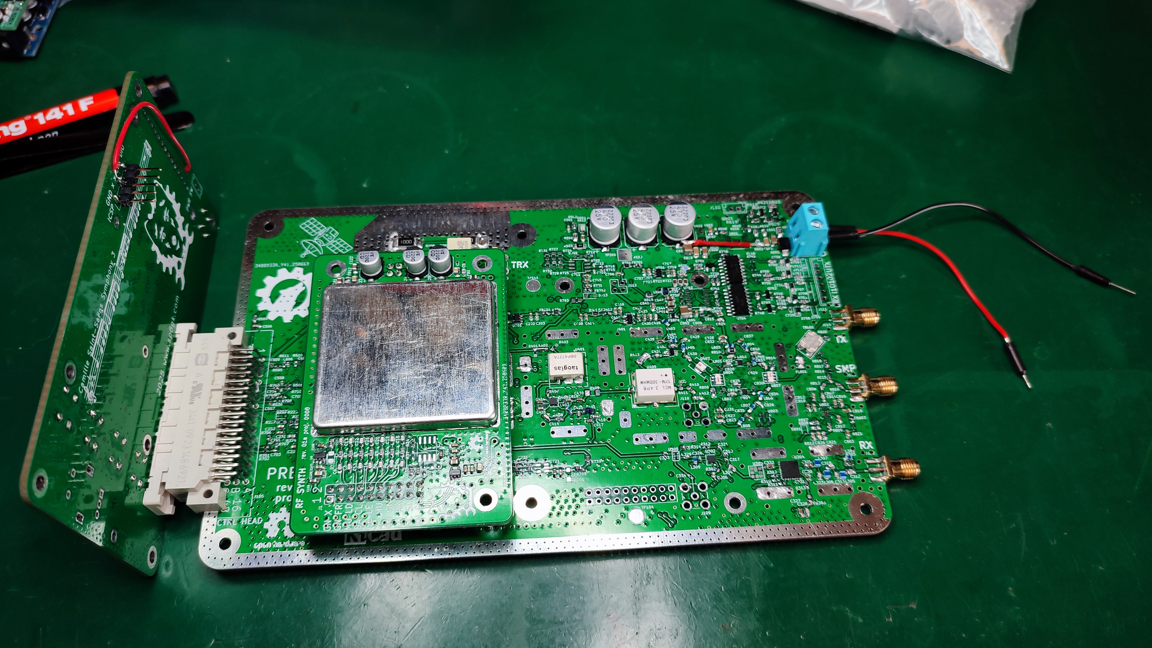
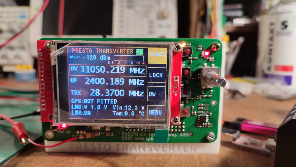
Presto uses STM32F411 as the main microcontroller, running C code with FreeRTOS. This offers good responsiveness of the graphical interface while maintaining the possibility to serve the interrupts in predictable time. For optimal use of mcu resources most demanding peripherals are also using DMA (LCD SPI which sends a lot of data, ADC which continuously samples many channels, UART which may receive or send a long string). The control head is the PCB that holds the actual microcontroller, LCD module attaches to it. In the receive mode the screen displays the down link frequency (DW), this is what LNB is actually tuned to. The up link (UP) is the transmit frequency that will be output in TX mode. Transceiver frequency (TRX) is a frequency to which an external transceiver should be tuned to. Tuning transceiver to the TRX ensures that the displayed uplink and downlink frequencies match the actual frequencies. Using the select button (second from the bottom) the user can select which frequency to change on the transverter. Transverter keeps track (top button) of the frequency offset from the TRX, therefore retuning of TRX is not necessary. In track mode no matter whether DW or UP is chosen, change of one will cause the same change in other. Disabling the tracking option allows for split operation where DW and UP can be changed individually. Choosing TRX as a selected frequency will change the transceiver frequency that the transverter is tuned to. Each change of frequency is saved to on board EEPROM.
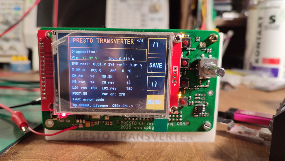
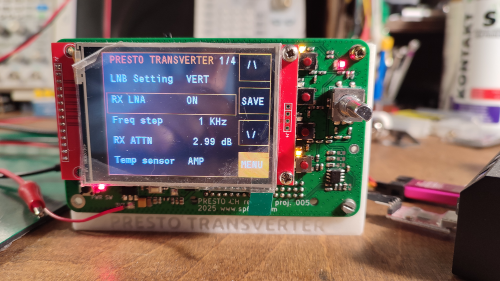
The menu button displays a scrollable list of options, using encoder it is possible to turn on LNA, set polarization of LNB, LNB LO, and similar settings. The final page of the menu shows diagnostics information like SW version, PCB revisions, voltage readings and such. The transverter runs a built-in self test on each startup and monitors power good lines and inner voltages for abnormalities.
Each PCB of transvert has its own EEPROM that stores serial number, project ID number, revision, configuration, last used settings etc... The control head also stores information such as power on times and last error codes. For reliability of reading proper configuration settings, CRC mechanism is used.
Main board exposes UART port thru optoisolators. Unfortunately optoisolators have proven to be too slow for this kind of application, next revision will use proper digital isolators. The serial interface can be used to remotely manage the transverter. Embedded software implements my simple interpreter that I called B.A.S.I.C. (Basic Automated SCPI Interpreter for Controllers). BASIC triggers on UART interrupt and processes SCPI like commands. SCPI commands are common in automation of test measurement instruments, they are very handy and natural in this type of systems since interface can be split into subsystems. Beside controlling the basic (no pun intended) settings such as frequency or polarization of LNB, BASIC also includes a service mode where access to EEPROM (POKE and PEEK) is implemented. Service mode can be used during production allowing for automated alignment and saving of calibration data.

sp6gk 'at' protonmail.com
Here is a demonstration of restored radio from 1938.

Almost assembled fully home made 2.4 GHz power amplifier on LDMOS transistor.

1.25 GHz small signal amplifier with open stub matching. Active element is BFP420 BJT.