Digitally controlled AM modulator

Description
Amplitude modulation (AM) is a very simple method of carrying the information over the distance.
AM was widely used in broadcast receivers so if you intend to restore vintage radios or want to learn basics of telecommunication
you might find yourself in a need for a reliable and precise AM generator.
This project combines old AM modulation with modern solutions. No custom coils are necessary, thus this project is perfect for
those who want to start their adventure with RF. This generator uses microcontroller to control direct digital synthesizer (DDS)
in order to create a carrier and balanced modulator IC to modulate the carrier with incoming input (3.5mm jack)
or 1KHz sine wave generated on board.
The microcontroller used is ATmega 328p, so it can be programmed as Arduino, with all the Libraries being easy to use.
Basic specification

- Frequency up to 12.5 MHz (limited by AD9833 master clock being 25 MHz)
- OLED LCD screen, 4 buttons
- 12V power supply
- Dimensions: 55x100mm
- Step selection, reprogrammed frequencies, last used frequency is restored
- Output level and modulation depth regulation.
- 3.5mm jack for audio input. SMA and 2.54mm gold pin output
- ICSP and TX/RX pins for programming and debugging
- Two LEDs for debugging
- Reverse voltage protection
- Arduino compatible, uses high level libraries
- Easy to program your own frequencies
Theory of operation
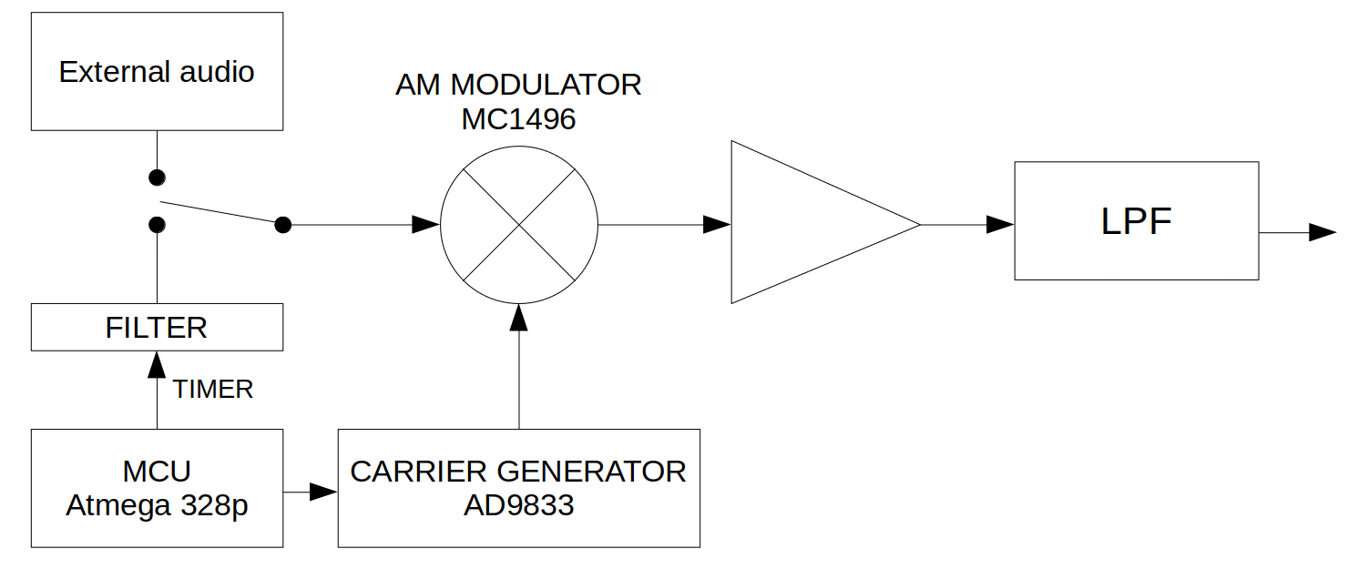
The developed circuit consists of both analog and digital parts.
Modulating signal (input) is a low frequency signal such as an audio signal and can be fed from external source such as signal generator or phone via 3.5mm jack or if no
connector is plugged, via timer of microcontroller (Atmega 328p) and a low pass filter
which shapes the PWM signal of 50% duty cycle and frequency of around 1KHz
to approximate sine wave. The input passes then through 100KHz low pass filter, a potentiometer for setting the modulation depth and a DC blocking capacitor.
Microcontroller is also responsible for changing the frequency of the carrier generator, the communication is carried over three wire SPI (serial peripheral interface). SPI interface is also used for driving the OLED screen. The microcontroller is reading state of four buttons, two for increasing and decreasing carrier frequency, one for changing step and one for entering memory mode.
The AD9833 is a direct digital synthesis integrated circuit meaning that it creates a waveform. This IC is using ROM which maps the phase of a sine wave to magnitude. External clock of 25 MHz is fed to the DDS IC so by the Nyquist-Shanon theorem we can generate up to 12.5MHz. Output of the DDS passes through an additional $\pi$ filter which shapes the discrete sine wave (reconstructive filter)
by the cost of bandwidth which will be limited by the LPF anyway.

The MC1496 is a balanced modulator it takes the modulating input signal and higher frequency constant amplitude carrier to produce an AM signal. The MC1496 requires well filtered supply rails. It also requires three bias voltages including a -10V negative rail. This necessitates a larger amount of external components. MC1496 can adjust the gain of its single end output, however the signal is not very strong. The output impedance is also 40K at 10MHz. In created circuit the AM signal from MC1496 at 1MHZ approximately 60mV when measured in circuit.
The AM signal is therefore amplified by an end stage amplifier. Class A with NPN transistor (BC847) is being used here. Since the prototype presented here is to be operational up to high end of a broadcast band (1500KHz) this universal switching transistor cuts the cost of using more expensive and less available RF FET which should be chosen for higher frequency design due to lower noise expected from the instrument itself or if the output stage must have specified impedance. Device designed in this project claims non of these characteristics leaving them for the more professional instruments.
The final element is a low pass filter which was designed as a two pi networks of LC components. These are common values that can be found in THT or SMD cases.
The values chosen in the prototype provide satisfying results for operation in the region of broadcast band, making the device useful for tuning the front ends of AM receivers. Notice however that SFDR might suffer if harmonics of lower frequencies are not attenuated by LPF.
The -10V power rail is created using MC34063 converter which is very easy to get and cheap IC capable of controlling boost, buck or inverter DC-DC converter.
The 10V rail is regulated using LM7810 in TO-220 or DPAK package, two footprints are present since DPAK version is not as common as TO-220.
The PCB is 50x100mm, this design has a ground plane around the board. The edges are also stitched with vias in equal distance to avoid fringing, traces are put further away from the substrate edge.
By default three frequencies are saved in EEPROM. Those frequencies can be common IF or tuning frequencies as 455KHz, 1.455MHz etc. To change the current frequency one should press memory mode to enter memory mode, then use frequency up or down to change channel and confirm new frequency by double pressing memory mode, single pressing the step button returns device to normal operation. EEPROM is also used for storage of recently used frequency.
The image with green PCB shows a prototype which uses ready AD9833 module, the AD9833 comes only in TSSOP package which might be tricky to solder for beginners. The MC1496 is also in a larger package, through hole DIP, this first version still uses TQFP for ATmega microcontroller, but overall the PCB is still bigger and has only two buttons and three LEDs.
Schematic

GitHub source code and gerbers
You can visit my GitHub repository in order to download Gerber, KiCad files and code that you can flash to the microcontroller.
Link
Measurements
Following are screens from a first prototype loaded with 370ohm resistive load. Green trace is the output, green is a carrier and blue is output from the balanced modulator IC.


Further ideas
Some ideas for next version:
- Change to AD9850 (higher frequency possible)
- Operation from LI-Ion battery
- 3D printed hand-held case